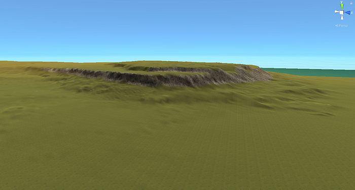
I recently got curious about using real-world elevation to model terrain inside a game engine. I spent several days trying to figure out how to take GIS (Geographic Information System) elevation data (or DEM data) and process it into a format that I could load into the Unity game engine as a heightmap. It took several days of reading tutorials and forum posts, but I eventually found a process that worked for me. I thought it might be useful to others as well.
The short version of the process is this:
- Find DEM (Digital Elevation Model) data for the area you are interested in
- Use GIS software to open the DEM data files
- Process the data in the GIS software to interpolate the elevation data
- Output the data and convert it into a RAW image format that Unity can use to generate terrain
Before we begin, you’ll need a few things:
- DEM data that you want to convert into a heightmap. For this post I’ll be using Ontario’s open DEM data. These file are actually DTM data. DTM (Digital Terrain Model) is a format that estimates true ground surface elevation and ignores buildings. You could also play around with data from USGS Earth Explorer (here are some instructions on using Earth Explorer)
- Some GIS software. I used an open source piece of software called QGIS. All the instructions below are for QGIS, but there are probably similar processes in other GIS software.
Disclaimer: I am not a GIS expert, I just read through a bunch of tutorials and forums posts to glean enough information to get the results I wanted. There may be better/more efficient ways to use GIS software to achieve similar results.
DEM Data
When you download DEM data, what you’re getting is a file that contains geolocation data, and elevation data inside an area. In the case of Ontario DTM data, each file contains a 1km x 1km area of information with a resolution of 2m x 2m per data point (pixel). The data is accurate to 1m in elevation. This is very accurate, but if you were to use this data directly as a heightmap, you would find that because each pixel represents whole meter elevations, you end up with big steps in your terrain.
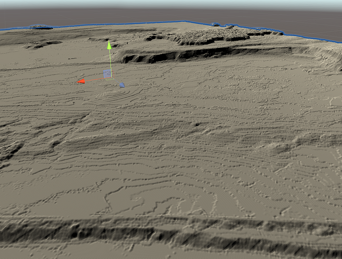
Most of the process documented below is about trying to find a way to smooth out that elevation data through interpolation.
Loading DEM Data in QGIS
The first step is to load your DEM data into QGIS. If you already have all your data in a single file, this is as simple as opening QGIS and loading the file (you can skip ahead to “Generating Contours”). However, if you’re using data like the Ontario DTM data, it comes split up into chunks that must be assembled into a single dataset for the area you’re interested in.
Determine which DTM package you need from the map of Ontario and download the corresponding package (these are about 3GB each and the download can take a while).
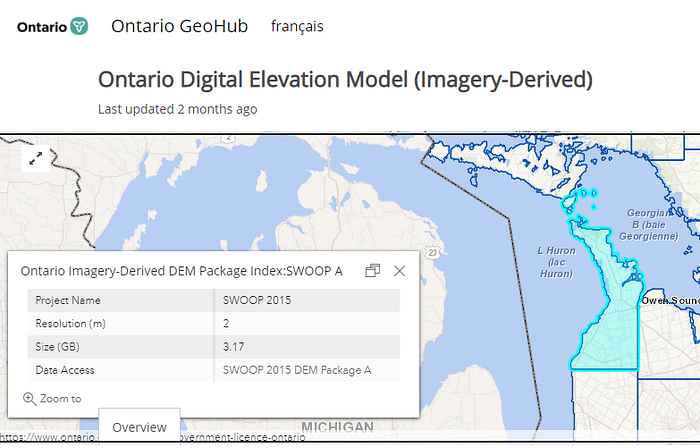
Download the Tile Index shape file (SHP) found under “Additional Documentation”.
Open QGIS with GRASS (note: QGIS has two executables, one called “QGIS Desktop” and one called “QGIS Desktop with GRASS”). You will need the GRASS processing tools, so make sure you open the correct exe.
Open the shape file in QGIS. You can do this by dragging the .shp file into the Layers window in QGIS, or selecting Layer > Add Layer > Add Vector Layer… and browsing to the file.

Once the shp file has loaded you should see a map of Ontario split up into 1km x 1km tiles:
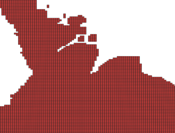
In the Layers window, right-click on the tile index layer and select “Properties…” In the Labels tab, change it from “No Labels” to “Single Labels” and set the Value dropdown to “TileName”:

If you zoom in on the tiles (mouse scroll wheel), you’ll find the file names for the individual DEM files you’ll need:
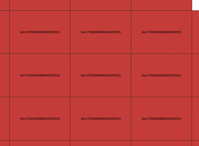
Drag each of the corresponding files you need into the Layers window, or add them from Layer > Add Layer > Add Raster Layer… (and find the file on your computer).
You should end up with something that looks like this:
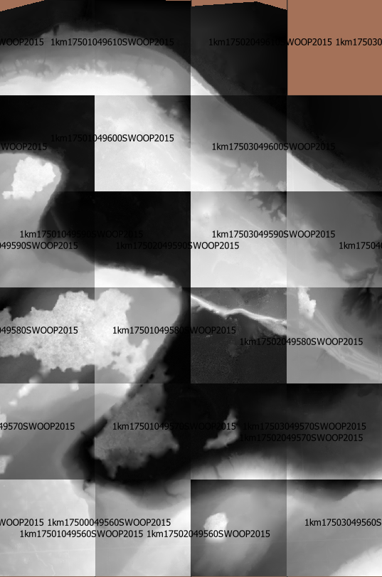
You can see that each file uses its own greyband, where black is the lowest elevation in that area and white is the highest.
Next, we need to merge all the data into one dataset that we can process as a whole. Select Raster > Miscellaneous > Merge… from the menus. In “Input Layers” click the “…” button and select all the layers you want to merge. Under “Merged” click the “…” button and select “Save to file…” and give the result a file name. Click “Run” and a new layer will be created with your merged result.
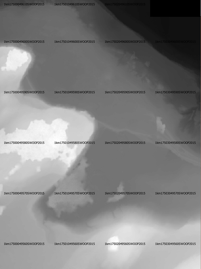
Looking good! However, at this point we still have fairly low resolution in terms of the various height values. Now we need to interpolate the height values to smooth things out.
Generating Contours
In order to interpolate the height data, we need to generate a vector representation of the raster data that we have so far. To do this, we’ll generate some vector contour lines that represent the surface mathematically.
Select the merged layer in your Layers window in QGIS. Then select Raster > Extraction > Contour…
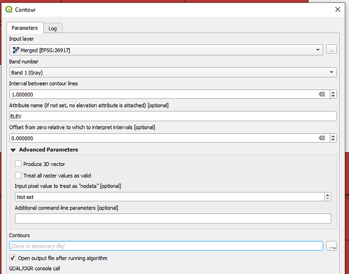
In the window that opens, set the “Interval between contour lines”. I used 1m, because that was the vertical resolution of the DTM data. The tighter the contour lines you generate at this point, the more accurate your interpolated surface will be. If you want a much smoother surface, you can make larger contour intervals (e.g. 5m). Also note that using a smaller contour interval will slow down the contour generation, but will speed up the interpolation step later greatly (see Note in “Forming a Raster Surface” below).
Make sure the “Attribute name” is set to “ELEV”. This tells the process to use the elevation data stored in the merged raster layer to generate the contours.
Under “Contours” click the “…” button and select “Save to File…” and choose a file name.
Click “Run” and wait for a bit. If your contour interval is small and your dataset is large, this can take several minutes to run.

Rasterize the Contours
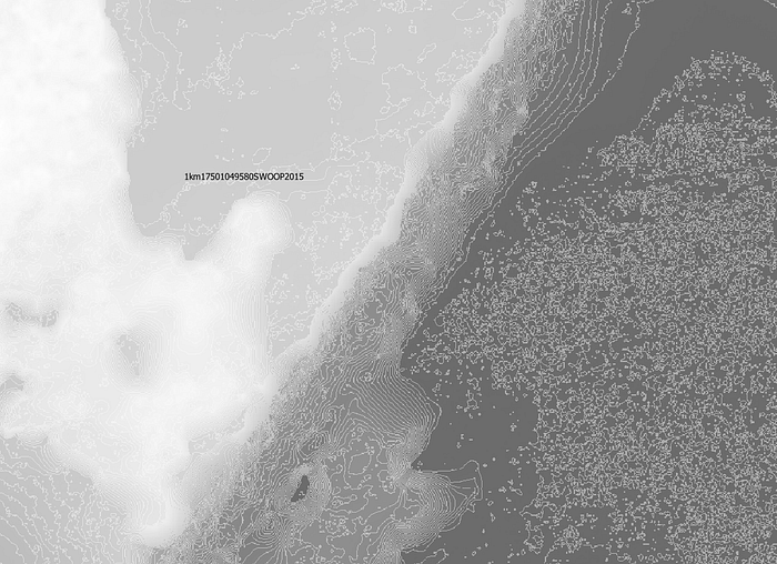
At this point we now have a vector layer that contains contour lines representing our surface. But in order to run the interpolation process, we need raster (pixel) contours. So the next step is to convert our vector contour lines back into raster contours.
Select the Contour layer we created in the last step. In the Processing Toolbox window (you might have to open this in View > Panels > Processing Toolbox) search for “v.to.rast” and open the GRASS tool with that name.
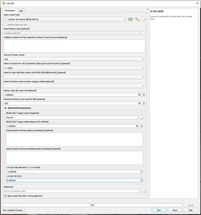
Make sure your Contour layer is set as the input layer.
Set “Source of raster values” to “attr”.
Set “Name of column for ‘attr’ parameter” to “ELEV”.
Set the “GRASS GIS 7 region cell size”. This is determining the resolution of the raster data you’re generating. I set this to 1, which generates a raster image that matches the resolution of the original data. The larger the cell size you set, the lower the resolution of the resulting image, but the faster the process will run.
Set the output to “Save to File…”
Run to generate the rasterized contour layer.
Rescale the Raster Contours
Ok, still with me? Good. Now we have rasterized contour lines, but they’re still no more accurate than our original data. The problem is that if we generate a surface from these contour lines, we’re still doing to get chunky results because there just isn’t enough room in the data for values between contour lines. So the next step is to rescale the contour lines and spread them out. Unity can load 16-bit heightmap images, so we’re going to take advantage of the 16-bits per pixel and expand the distance between each contour line’s height so that we can interpolate with more detail between them. For example, if we have contour lines at 10m, 11m, 12m, etc, we’ll rescale them to be at 10m, 110m, 120m, etc to give more room between them.
Select the raster contour layer you created in the last step, and in the Processing Toolbox panel search for “r.rescale” and open the tool.

Make sure your raster contour layer is selected as the Input.
Set the input data range to match the min/max values for the raster contour layer (the two values found under the layer name in the Layers window).
Set the output data range to something much larger (e.g. 0–15000). Just don’t exceed 0–65k, as you’ll be exceeding the values that can be stored in a 16-bit number.
Leave the cell size as 0.0 (default).
Select “Save to File…” and Run.
The result should be a layer with contours with new colouring.

Forming a Raster Surface
Finally! Where the magic happens. Now that we have rescaled our raster contour lines, we can generate a raster “surface” from those contour lines using QGIS.
In the Processing Toolbox panel search for “r.surf.contour” and open the tool.

Note: this particular tool uses flood fill for each pixel in the area to determine the best height for each pixel. The docs warn that having large open areas leads to exponentially longer calculation times. This is why I mentioned above that having tighter contour lines speeds up the interpolation process. If you have big gaps between contour lines, this tool can literally take hours to run.
In the r.surf.contour window make sure your rescaled contours layer is selected as the Input.
Set the “GRASS GIS 7 region extent” to match the contour layer.
Set the cell size. Note: the smaller cell size, the longer this will take! But the larger the cell size, the chunkier your resulting data will be. On my PC, running with a cell size of 2 on a 4km x 6km area of land and 1m contour intervals takes about 20 mins. With 5m contour intervals, it takes 2.5 hours.
Select “Save to File…” and select your output file.
Run and wait (and wait, and wait). On my computer the progress bar sits a 0% complete until it’s done, so you just have to be patient.
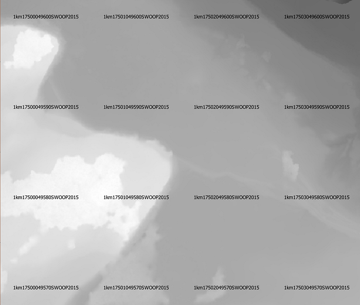
At the end you should have another greyscale raster layer in your project. Except now it contains much smoother data (which is hard to see just looking at the image).
Convert Result to RAW Format
Cool! We have the actual data we need for our heightmap. There’s only one more step, and that’s to convert this data into a RAW image format that Unity can load. For this, you need to run a tool on the command line. On Windows I like to use the PowerShell. You can access this by pressing Windows-X and selecting Windows PowerShell.
Navigate in your shell to the directory where your file from the last step was saved (it’ll be a GeoTiff file with a .tif extension) and execute this command:
C:\OSGeo4W64\bin\gdal_translate.exe -of ENVI -ot UInt16 <raster_result_filename>.tif <output_heightmap_filename>.raw
Note: This assumes QGIS was installed in the default directory on Windows 10 64-bit. If you installed it somewhere else, use the appropriate path to the gdal_translate.exe.
This will generate a RAW file with the name you specified in the command. This RAW file can be loaded by Unity’s terrain system!
Unity Terrain
We’re almost there!
Now open a Unity project and scene. Add a Terrain object to the scene by selecting GameObject -> 3D Object -> Terrain.
Click on the terrain in the scene to select it. In the Inspector window click on the Terrain Settings button in the Terrain component (it has a gear icon).
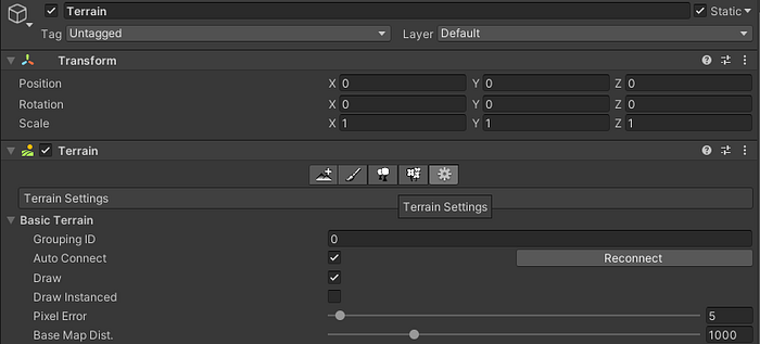
Scroll down in the Inspector window through the Terrain Settings to find the section called “Texture Resolutions (On Terrain Data)”. Under “Heightmap Resolution” is an “Import Raw…” button. Click that and find the RAW file you exported in the previous step (it does not need to be inside your Assets folder).
This will open the Import Heightmap window. Make sure Depth is set to “Bit 16”. Set the resolution to match the x-dimension of your RAW image (in my case, 2000 pixels). Byte order to Windows. And make sure the “Flip Vertically” toggle is on. For me I was seeing the heightmap flipped on import.
Set the Terrain Size to match your real world dimension (in my case 4000m x 6000m).
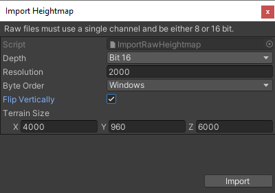
Click “Import” and the terrain shape should update for your heightmap.
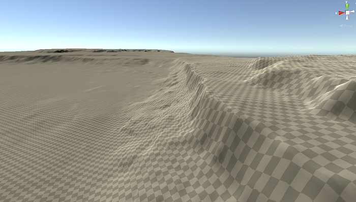
You may need to play with the Height setting in the “Mesh Resolution” of the Terrain component inspector. Because we expanded the height range of our contours, it’s not a 1:1 with real height anymore. I picked an area of the heightmap that I could identify in the Terrain and measured the height in Unity and compared it to what the DEM data said the difference should be and adjusted accordingly.
You might also need to adjust the Heightmap Resolution in the Terrain inspector to balance performance with accuracy.
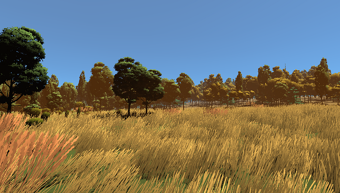
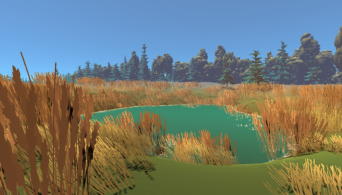
After that, you can add a terrain material, paint some ground texture on, and start decorating your scene! Phew! You did it!
Owen Goss is one-half of Milkbag Games, a two-person indie studio based in Ontario, Canada. They have made games like Disco Zoo, FutureGrind, and SantaCraft.


